Thursday, November 8, 2012

Arduino PID Temperature Controller and Sous Vide

Project Objective: To design a PID temperature controller using the Arduino and apply it to Sous Vide.

Introduction: This all started as a project to control beer brewing which is still in the works. In order to get there, there are a series of projects which can be used to break the problem down into workable pieces. Basically, brewing beer requires heating liquids contained in kettles and then moving the liquid from kettle to kettle. So what is needed is a way to heat the liquid to a controlled temperature and then turning pumps on and off. So what do we need:
  • Kettles with heaters, fittings and pumps.
  • An electronic controller with PID capabilities.
A single kettle version of this is what is need for a Sous Vide system including a small pump to keep the temperature of the water, uniform.

Interesting Links: Before we get started here are some useful links on this subject.

  • Lower East Kitchen:  On this site you will find a kit for a PID controller design for Sous Vide. Though the controller can be used for any water bath they suggest using a stainless coffee  urn available from Amazon for $25. 


PID Controller: A Arduino based PID temperature controller has been developed by Brett Beauregard and Rocket Scream Electronics called the osPID.  This design was predated by the Reflow Oven Controller Shield available from Rocket Scream


Sous Vide Hardware:


To Be Continued: 11/8/12

Thursday, September 20, 2012

Arduino as Serial LCD Display


Project Objective: In this project we will use the Arduino to emulate the PH Anderson #117 serial text display minus big numbers. The layout of a piggyback pcb will complete the  project.

Introduction: See the discussion in the "Controlling a Serial Display" project which covers several of the serial LCD displays on the market. Most of these products have a similar command set and the sketch presented here could be modified to emulate many of these.

Serial LCD displays are available in both text and graphic versions. This project covers text displays with one to four lines and up to 40 columns. Initially, the displays will be limited to 80 total characters, a limitation of the Arduino standard LCD library.

Since the serial LCD is a one wire device, all control of the LCD terminal must use command sequences. Here are the commands used in this project:


Arduino Serial LCD Rev. A: Command Set (as of 9/16/12)
Command 
?a home cursor
?b destructive backspace
?c# set cursor style,   0= none 2= blinking 3=underline
?f clear screen
?g Beep 
?h Backup Cursor (Non-destructive backspace)
?i Forward cursor
?j Up cursor
?k Down cursor
?l Clear cursor line
?m Carriage Return
?n CRLF, cursor at start of next line, line cleared
?p### Position cursor x = ##, y = #
?x##  Position cursor on x column, (two characters are required), first column is column 0, 
?y# Position cursor at y row, first row is row 0 (one character only)
?? display a "?"
?! Send direct command to LCD
?B Backlight Intensity – sets PWM value, two hex digits req. (00 to FF)
?D#      Define custom character. See text.
?# Print a custom character
?H High output on auxiliary digital pins: valid numbers are 1,2,3,4
?L Low output on auxiliary digital pins: valid numbers are 1,2,3,4
?G Configure for LCD geometry. Supported formats: 2X16, 2X20, 2X24, 2X40, 4X16 and 4X20.


Except for the ?p### command they are identical to the PH Anderson, #117 chip. The start character for a command sequence is a '?', but this can be easily changed in the sketch, say to a '!'. The sketch below compiles, but some commands are missing.

One of the nice features of the #117 command set is that control can be accomplished using a PC termial program. In fact, using the Arduino IDE to update the code the built in terminal can be opened to test changes.The piggyback pcb can be modified and updated the same way.

Note: As of 10/08/12 the code was updated, as well as the schematic.The schematic changes were made to simplify the piggyback pcb layout. Because of this there were also changes to code. Several additional commands have been added and we will continue to add more.


Schematic Used with Solderless Breadboard:


The schematic above shows the parts which need to be added to the solderless breadboard for this project. The headers in the schematic are the the headers on the Arduino board. The piggyback board will require a different schematic and include the atmega328, as well as, serial interface circuits and jumpers.

The image below shows the Arduino Serial LCD connected to an Arduino sending serial data at 9600 baude. The text being sent is "Temperature" and "76.8" or "77.6", where the word Temperature is sent once and the numbers sent alternately in the loop section of the sketch. Before the numbers are sent the cursor is positioned at character column 14. The small round object is a piezo speaker.


Arduino on left is sending serial data to Arduino on right.


Sketch:Version  0.6


/*
Arduino_PHAnderson #117 Serial LCD emulator
Date: 10/08/12
Author: R. LaSalle

*/

#include <LiquidCrystal.h>
#include <EEPROM.h>

/* LCD pin assignments
RS 8
RW 9
E  10
D4 4
D5 5
D6 6
D7 7
*/

#define BP 3
#define BL 11
#define Bd0 14
#define Bd1 15

#define maxrowloc 0
#define maxcolloc 1
#define bootscrloc 2
#define curtypeloc 3
#define ledblloc 4
#define tabloc 5
#define user0 10
#define user1 30
#define user2 50
#define user3 70

#define commchr '?'
//#define VER .5

uint16_t bauderate = 9600;
uint8_t maxrow = 4;
uint8_t maxcol = 20;
uint8_t bootscr = 1;
uint8_t ledbl = 0x7f;
uint8_t nrow =0;
uint8_t ncol =0;
int8_t temp =0;
int8_t temp1 =0;
int8_t temp2 =0;
int8_t temp3 =0;

LiquidCrystal lcd(8,9,10,4,5,6,7);

void setup() {
//  EEPROM.write(maxrowloc,0);
//  EEPROM.write(maxcolloc,0);
  temp=EEPROM.read(maxrowloc);
  temp1=EEPROM.read(maxcolloc);
  if(temp==0 && temp1==0){  //Is EEPROM empty? If yes load defaults.
    maxrow=4;
    maxcol=20;
    EEPROM.write(maxrowloc,maxrow);
    EEPROM.write(maxcolloc,maxcol);
  }
  maxrow=EEPROM.read(maxrowloc);
  maxcol=EEPROM.read(maxcolloc);
  lcd.begin(maxcol,maxrow); // Change this for other screen sizes.
  pinMode(Bd0,INPUT);  //bauderate set bit 0
  pinMode(Bd1,INPUT);  //bauderate set bit 1
  digitalWrite(Bd0,HIGH);  //pullup
  digitalWrite(Bd1,HIGH);  //pullup
  if(digitalRead(Bd0)==LOW && digitalRead(Bd1)==LOW){bauderate=2400;}
  if(digitalRead(Bd0)==HIGH && digitalRead(Bd1)==LOW){bauderate=9600;}
  if(digitalRead(Bd0)==LOW && digitalRead(Bd1)==HIGH){bauderate=19200;}
  if(digitalRead(Bd0)==HIGH && digitalRead(Bd1)==HIGH){bauderate=38400;}
  Serial.begin(bauderate); // Default baudrate.
  pinMode(BL,OUTPUT);
  pinMode(BP,OUTPUT);

  analogWrite(BL, ledbl); // Set maximum brightness.

// Boot Screens
  if(bootscr==1){    //Config screen
    ncol=0;
    nrow=0;
    lcd.setCursor(ncol,nrow);  //home cursor
    lcd.print("Arduino_PHA117");
    lcd.setCursor(0, 1);
    lcd.print("G:");lcd.print(maxrow);lcd.print("x");
    lcd.print(maxcol/10);lcd.print(maxcol%10);
    lcd.print(" B:");lcd.print(bauderate);
    lcd.setCursor(0,0);  //home cursor
  }
}

void loop() {
  byte rxbyte = getc(); // Command
//byte temp; // Parameter

  if (rxbyte == commchr) {
    switch (getc()) {
    case 'p': // Set cursor position (2 parameters, column, row)
 temp=getn();
 temp1=getn();
          temp2=getn();
          if(temp=='e'||temp1=='e'){
            error();
            break;
          }
          temp=temp*10+temp1;
          if(temp>maxcol-1){
            error();
   break;
 }
          ncol=temp;
            if(temp2=='e'){
             error();
            break;
           }
           if(temp2>maxrow-1){
             error();
            break;
           }
            nrow=temp2;                
      lcd.setCursor(ncol, nrow);
      break;
    case 'a': // Cursor home (doesn't clear the screen!)
      lcd.home();
      ncol=0;
      nrow=0;
      break;
case 'b': //Destructive backspace
 lcd.command(16);  //cursor back
 lcd.write(' ');    // write space
 lcd.command(16);  //cursor back
 ncol=ncol-1;
 break;
    case 'c': // Set Cursor type
      switch (getc()){
        case '0':
          lcd.noCursor();
          lcd.noBlink();
          break;
        case '2':
           lcd.cursor();
           lcd.noBlink();
           break;
        case '3':
            lcd.cursor();
            lcd.blink();
            break;
           default:
           break;
        }
        break;
    case 'f': // Clear screen
      lcd.clear();
      ncol=0;
      nrow=0;
      break;
    case 'g': //beep
      tone(BP,4000,250);
      break;
    case 'h': // Move cursor back
      if(ncol>0){
lcd.command(16);
ncol=ncol-1;
      }
      break;
    case 'i': // Move cursor forward
if(ncol<maxcol){
lcd.command(20);
 ncol=ncol+1;
}
      break;
    case 'j': //Cursor up
if(nrow>0){
 nrow=nrow-1;
 lcd.setCursor(ncol,nrow);
}
     break;
     case 'k': //Cursor down
if(nrow<maxrow){
 nrow=nrow+1;
 lcd.setCursor(ncol,nrow);
}
      break;
      case 'l':  //clear cursor line
        ncol=0;
 //       maxcol=20;
        lcd.setCursor(ncol,nrow);
        for(byte i=0;i<=maxcol-1;i++){lcd.write(' ');}
        ncol=0;
        lcd.setCursor(ncol,nrow);
      break;
      case 'm':  //CR
        ncol=0;
        lcd.setCursor(ncol,nrow);
      break;
      case 'n':  //CRLF
        ncol=0;
        if(nrow<maxrow-1){nrow=nrow+1;}
        lcd.setCursor(ncol,nrow);
      break;
      case 'x':
          temp=getn();
          temp1=getn();
          if(temp=='e'||temp1=='e'){
            error();
            break;
          }
          temp=temp*10+temp1;
          if(temp>maxcol-1){
            error();
   break;
 }
          ncol=temp;
          lcd.setCursor(ncol,nrow);
break;

case 'y':
          temp=getn();
           if(temp=='e'){
             error();
            break;
           }
           if(temp>maxrow-1){
             error();
            break;
           }
            nrow=temp;
            lcd.setCursor(ncol,nrow);
        break;
       case 'B':
         temp=geth();
         temp1=geth();
         if(temp==0xff || temp1==0xff){break;}
         temp=temp<<4;
         ledbl=temp+temp1;
         EEPROM.write(ledblloc,ledbl);
         analogWrite(BL,ledbl);
       break;
       case 'G':  //enter R,C
         temp=getn();
         temp1=getn();
         temp2=getn();
         if(temp=='e' || temp1=='e' || temp2=='e'){error();break;}
         maxcol=temp1*10+temp2;
         maxrow=temp;
         EEPROM.write(maxcolloc,maxcol);
         EEPROM.write(maxrowloc,maxrow);
       break;
    }
  }
  else{
  // Otherwise its a plain char so we print it to the LCD.
  lcd.write(rxbyte);
  ncol=ncol+1;
  }
}

/*
 * Waits for a byte to be available, reads and returns it.
 */
byte getc() {  //get character
  while (Serial.available() == 0);
  return Serial.read();
}

byte getn() {  //get decimal digit
  byte temp;
  while (Serial.available() ==0);
  temp=Serial.read()-48;
  if(0>temp>9){
    return 'e';
  }
  else{
  return temp;
  }
}

byte geth(){  //get hex digit
  byte temp=getc();
  if(temp>=0x30 && temp<=0x39){
    temp=temp-0x30;
    return temp;
  }
  if(temp>=0x61 && temp<=0x66){
    temp=temp-0x57;
    return temp;
  }
  return 0xff;
}

void error(){
  tone(6,4000,250);
  return;
}


.

To Be Continued

Tuesday, July 3, 2012

uLab40AVR, the ATmega1284P for Solderless Breadboard

Project Objective: The uLab40AVR is designed to be functional similar to the uLab28AVR.

Introduction: This PCB is designed to be a mate to the Daiduino except that it uses the Sanguino pin designations. This will not cause a problem because of the Arduino IDE pin maping. For example, if you connect a LED/resistor to D13 on the uLab40AVR and the Daiduino, then select the appropriate board in the Arduino IDE, the blink sketch will work.

Specifications:

  1. Use of thru hole parts except for regulators
  2. Dual regulators for 5V and 3.3V
  3. Use a breakout boards for serial communication, USB or RS232
  4. Power switch
  5. Use jumpers for selecting power source.
  6. 36 pin header for signals and two separate pin sets for powering the SLBB.


Note: The design is not complete. 7/3/12

uLab28AVR, Arduino for Solderless Breadboard

Project Objective: To transpose the Arduino to a solderless breadboard plugin.

Introduction: This board has all the features of the GMduino, Arduino clone, shown on another post. The digital and analog pin designations are identical to the GMduino and, therefore, the Duemilanove. In addition, the ATmega328P pin designations are also shown.

Specifications:
  1. Use of thru hole parts except for regulators
  2. Dual regulators for 5V and 3.3V
  3. Use a breakout boards for serial communication, USB or RS232
  4. Power switch
  5. Use jumpers for selecting power source.
  6. 25 pin header for signals and two separate pin sets for powering the SLBB.


GMduino, a Buildable Clone

Project Objective: Design a Arduino clone that is easy to assemble for clubs and beginners

Introduction: With the criteria of ease of assembly, the first problem is the FTDI USB chip which even for the experienced assembler is not an easy mounting task, but the availability of small FTDI breakout boards solves the problem. I am using the BUB II by Modern Devices since they leave the connector for you to assemble which I add underneath the board.. Adafruit has the Friend, but it is pre-assembled with the connector on the top.

The standard 7805 type regulator is real-estate hungry and two will be needed, so surface mount LDO regulators are used. These are three pin devices and mounting is not difficult. Low drop out, LDO, devices are used to limit heat dissipation. In fact, we use a 6V wall power supply which at low current has a 8.5VDC output where a 9V wart is at 12VDC.

The commercial Arduino uses a circuit for switching between external power, wart, and USB which can take up surface space unless smd parts are used. Further, it would be nice if RS232 serial communiction could also be used which means the clone would need to supply power to that breakout. So we opted for jumpers for both power selection and board voltage. In addition a power switch was added for convenience during development and if not wanted can be jumpered out.

Finally, a vertical reset switch is placed at the front of the board as well as the LED's. This means that with a shield mounted on the Arduino the reset button is still accessible and the LED's can be seen.

Specifications:
  1. Use of thru hole parts except for regulators
  2. Dual regulators for 5V and 3.3V
  3. Use a breakout board for serial communiction
  4. Place LED's and reset switch at front of board
  5. Add power switch
  6. Use jumpers for selecting power source.

GMduino with BUB II. Note the mounting position of BUB II connector.


Friday, June 22, 2012

GMduino II, Arduino Clone with RTC and EEPROM

Project Objective: To design an Arduino clone with through hole parts for easy assembly. The clone also includes an on board real time calendar clock with battery backup and an EEPROM. The board should operate at 5V and 3.3V including the RTC.

Specifications:
  1. Arduino clone with stacking connectors
  2. MCU: ATmega328P with Optiboot
  3. Through hole parts, except for regulators
  4. Serial communication using breakout boards
  5. Dual ldo regulators for 5V and 3.3V
  6. Power :input:  6V to 9V wart or USB jumper selectable
  7. Power switch
  8. Auto reset defeat switch
  9. On board I2C, EEPROM and RTC with battery backup.
  10. Vertical reset and ISP at front
Introduction: The project is an outgrowth of the Rainwater Monitoring System , RMS. The original development was done with the uLab28 PIC, then resulting in the Picduino. The RMS is basically a water tank level data logger with LCD display and keyboard.


Note: Layout complete ready for BatchPCB, GMduino.03C

Under construction

Thursday, June 14, 2012

Daiduino, an Arduino form with the ATmega1284P

Project Objective:
Wouldn't you like to have an Arduino that had 4 times the code capacity, more IO pins and used standard shields, but was only slightly larger? So would I. Further, I would like it to use through hole parts, so that it could be assembled as a kit. By the way, dai is a japanese word that means great or big. So Daiduino is a big Arduino but not a mega Arduino.

Discussion:
I started my Google search, looking at the Sanguino which uses the ATmega644P and has 64k bytes of code space, but soon found the ATmega1284P which has the same pinouts and 128k code space. As a matter of fact the Atmega1284P can be used on the Sanguino pcb. Another interesting item is that there is only 6 cent difference in price. Update: Downloading the Sanguino ZIP file indicated that the ATmega1284P is also included in their design.

Maniacbug site has the most useful data for this project and, in particular, have integrated the ATmega1284P into the Arduino IDE 1.0 environment. So the next step is to determine board size and pin assignments. Since I have already designed a through hole Arduino clone, transfering the power section to the Daiduino will be the first step. That process created a board 3.4" by 2.1".

For pin assignments, there are two designs on the Web to look at, Calunium and Bobuino.. Of the two the Calunium can use a standard shield, but is only USB powered. There is limited information on the Bobuino, but Maniacbug includes it in his zip file.

Specifications:
  1. Same width as the Arduino but longer, 2.1" by 3.5"
  2. Basic set of stacking connectors, UNO
  3. Dual regulators for 3.3V and 5V
  4. Power source: USB or wart
  5. USB interface on a plug in, such as a BUB II
  6. Through hole parts with the exception of the regulators.
  7. LED's, reset switch and ISP at front of the board
  8. Jumpers A4, A5 to I2C for UNO compatibility
  9. Jumper Auto Reset
Note: First version PCB ready for Batchpcb, 06/18/12. Ordered 06/19/12

Working

Friday, May 18, 2012

Bootloaders: How they Work.

Micro controller units are devices which contain a processing unit, programming and data memory and I/O. Early MCU's could not modify its program memory only the data memory. The program memory of present day MCU's can be modified with an in circuit programmer - ISP or ICSP - thru designated pins on the device or by the processor using special instructions.

A bootloader  is firmware, usually written into upper memory, which is executed when the MCU is reset. Typically, on reset, the bootloader waits for data to be input on the serial port and if this does not happen in a few seconds the bootloader jumps to the previously loaded code. If the data does start flowing, it is checked for correct protocol and loaded into program memory. The Atmel ATmega and the Microchip 18F MCU's handle bootloaders in a similar way.

A bootloader PC application interfaces with the MCU using the serial port. Before using the pc app to download the hex code, the reset switch at the MCU must be pressed. This sequence can be simplified by the PC application first triggering the serial port's DTR signal which at the MCU is connected to the reset pin. On the Arduino this is called auto reset.


Sunday, May 13, 2012

Programming the Optiboot into the ATmega328

I have been using the PicKit2 and a ZIF socket to program the 18F series of MCU. This setup is inexpensive and handy. I would like to have a similar setup for use with the Atmel mcu's.

USBasp: The least expensive ATmega in circuit programmer, ISP,  I have come across is the USBasp which is sold on many sites and all seem to be by different unknown manufacturers. The USBasp sold by HobbyKing for $4.50 had good reviews and a cable with both 10 pin and 6 pin connectors. The Arduino boards, as well as my designs, use a 6 pin ISP connector. I also located 28 pin, 0.3" ZIF sockets made by Textool,  # 228-3341, which I cannot find in the Textool datasheets since it has been discontinued.  I ordered and have received 2 sockets and they indeed have that number. Here are some sources for the USBasp:
  1. HobbyKing of HK: USBasp programming device for Atmel processors
  2. XHeli: KK control board USBasp
  3. Fun4diy: USBasp kit
  4. ProtoStack: USBasp AVR Programmer
Except for the HobbyKing unit all the USBasp above have 10 pin cables so that a 10 pin to 6 pin adapter will be needed. If you are good at making IDC cables you can make a cable similar to HobbyKing's.

EMS ISP Shield:  Evil Magic Science makes a Arduino shield kit that contains a ZIF socket and can be used with the Arduino ISP sketch to program bootloaders into ATmega MCU's. Adafruit sells a similar kit. The bare pcb from the EMS kit, which is sold separately, could be used as a standalone ZIF board with the USBasp to do the same thing.

OptiLoader: This sketch, which can be found here, turns a Arduino board into a stand alone optiboot programmer. The sketch contains images of OptiBoot hex files for several ATmega devices. When the reset switch is pressed, OptiLoader looks at the attached ATmega device to determine what it is and then programs it with the correct OptiBoot. While doing this, sequence data is sent out the serial port which can be monitored with the Arduino IDE serial communication tool.

For a setup using solderless breadboards look here. My setup will use a modified Evil Mad Science ISP shield, purchased as a bare pcb, and an Arduino Duemilanove

AdaLoader: This sketch, which can be found here, is based on the OptiLoader, but uses LED's and a beeper as progress feed back. The AdaLoader sketch has only one bootloader image and the LadyAda site describes how to change the image. The AdaLoader uses LED's for PROG and ERROR connected to pins A0 and D8, respectively, and a beeper to indicate program completion at pin A3. To program the bootloader press reset after loading the ATmega into the ZIF socket assuming your using the ISP shield.

ArduinoISP: This sketch which is part of the Arduino IDE download and can be found in the Examples folder turns an Arduino board into and AVRISP programmer. The ArduinoISP uses LED's for PROG, ERROR and HEARTBEAT connected to pins D7, D8 and D9, respectively.

ArduinoISP2: This sketch which is available at LaydAda is based on the ArduinoISP sketch, but has been modified to work with Arduino IDE 1.0. The ArduinoISP2 uses LED's for PROG and ERROR using A0 and D8. A beeper connected to A3 signals program complete. To program the ATmega328P device, first, dowmload the ArduinoISP2 sketch to the Arduino, then using the IDE do Tools > Burn Bootloader > w/Arduino as ISP. The green LED will light indicating the bootloader is being loaded. When loading is complete the green light will go out and the IDE will show "Done burning bootloader".

EMS ISP Shield Modifications:
Changes
  1. Cut land from reset switch and connect switch to Arduino Reset pin.
  2. Cut land from anode of Hello LED and connect to A0 pin.
  3. Add beeper and connect to pin A3.


New ISP Loader Shield
Project Objective: To design a shield which can be used with all of the above sketches.


Specification List:
  1. 28 pin ZIF socket
  2. Reset switch paralleling Arduino board reset switch
  3. Power switch for socket
  4. Both 6 and 10 pin ISP connectors with target power jumper
  5. LED's for PROG, ERROR and HEARTBEAT
  6. Beeper
  7. Serial LCD connector
The PCB for the new ISP shield has been received and assembled. The shield was plugged into a Duemilanove, the Arduino IDE 1.0 loaded, the Arduino ISP compiled and downloaded. Using the Tool menu, Burn Bootloader was selected and got a AVRdude sync error. I shifted to IDE 0023 with same results. From reading the web, this is a Auto reset problem. At this point I substituted my home grown Arduino clone, GMduino, described elsewhere in this blog. The only real difference between my clone and the commercial boards is the use of a .1uf capacitor for the auto reset circuit and a switch to disable auto reset.. The commercial boards use a resistor. Using the IDE 0023 I programmed ATmega328P device right off. Not only that, disabling auto reset was not necessary. Is it the capacitor? More testing.


ISPL Shield Rev A
Schmatic:

ISP Loader Shield Rev B

Problems with AutoReset: Normally, before a sketch is downloaded to the Arduino the serial port DTR signal  triggers which cause a reset and the bootloader to execute. AVRdude when it connects to the Arduino board also triggers DTR on the serial port causing an Auto Reset.


Still working on this. 6/6/12


Sunday, May 6, 2012

USB FTDI Breakout Problems

Since many of my projects use a USB FTDI breakout with a 6 pin output connector, I have been examining the available breakout boards.  At the same time I have been examining the Optiboot loader for the Arduino which has added additional questions about these breakouts. To date, the only breakout I have purchased is the Basic USB FTDI breakout DEV 09716 from Sparkfun.

First, a study of the FTDI chip shows a pin, VCCIO, which control the interface signal levels for the chip. This pin should be tied to 5V, if driving a 5V devices such as the PIC 18F2520 and the ATmega328, or to 3.3V for 3.3Vdevices. If left unconnected, it defaults to 3.3V. On the Sparkfun it is left floating and a work-around is not easy; therefore, the DEV09716 produces 3.3V signals when driving a 5V ATmega or PIC device. Modern Device has found that with the Optiboot this can lead to download problems.

Though I do not intend to power my development boards from the USB, for those who do, you should noted that the USB can source a maximum of 500ma at 5V, and a maximum of 50ma at 3.3V from the internal LDO regulator on the FTDI chip. Considering the way I will use these breakouts, it would be more useful to tie the power pin of the breakout to VCCIO. Doing this would make sure the interface voltage of the FTDI chip matches the MCU being used; however, in this configuration the breakout could not power the PCB. From the schematic, the Amicus processor card uses this method, that is VCCIO of the FTDI chip tied to the VCC of the 18F25K20. Since the FTDI chip is on the Amicus PCB, the USB can power the board and, since they have an onboard  3.3V regulator, they do not have the current limit problems.

A final requirement for the USB breakout for use with my boards is that the output connector be mounted on the bottom of the breakout as with the Sparkfun DEV 09716.

Here are my recommendations for USB breakouts:
  1. Modern Device, BUB 1 @ $14.. This unit makes it possible to connect up just about any way you want. Because of this it is bigger than the competition. This unit has a poly fuse and a ferite filter.
  2. Modern Device, BUB 2 @ $14. Similar to Friend with addition of an on board 3.3V optional regulator. The output connector is right angle and is shipped unsoldered. Fused.
  3. Adafruit, USB Friend @ $14.75. For my uses this has all the jumpers, as solder bridges, that I need. No fuses or filters.
  4. DFRobot, DFR0065 @ $15.95 from Jameco. This seems to be alright but I have asked some question of DFRobot so we will see what their answers are. Poly fuse.
Whatever unit I purchase it will be tested in several projects and will be reported here.

Monday, April 30, 2012

uLab 28 PIC


PROJECT OBJECTIVE: A PIC 28 pin processor board for use with slbb's. The board plugs into the slbb and incorporates an adjustable regulator for 5Vand 3.3V, a serial communication connector, ICSP, Picaxe and BasicAtom interfaces.

INTRODUCTION: This device was developed to expedite the setup of projects on a solderless breadboards for 28 pin PIC processors including Picaxe and BasicAtom.

Power: A single adjustable LDO regulator provides 5V and 3.3V jumper selectable, switchable power. The switch in its off position shorts the circuitry to ground for a clean shutdown. A green LED indicates power on.

Programming: The processor can be programmed in-circuit using the Tiny bootloader with the communication port or ICSP . When using the ICSP, the programmer, such as the PicKit2, should not be used to power the processor because of the shorting switch. If a Picaxe or BasicAtom part is being used, then programming is by the appropriate comm connector.

Communication: The communication interface is not provided on-board, but requires and appropriate breakout device for RS232 or USB to TTL conversion. A RS232 SMD breakout board is included as one of our projects, with pcb and kit available for those using PC com ports. The FTDI USB to TTL cable available from Mouser will work with Tiny bootloader which requires RTS on pin 6 for auto-bootloading. (We believe that Amicus requires DTR on pin 6.)

Testing: A single red LED is provided for quick setup testing. A single momentary switch is also provided.

FEATURES:
  • Header for plugging the I/O ports to a slbb
  • Each port pin marked to ease jumper connection
  • Mating pins to the slbb power busses
  • 3.3V and 5V selectable power with switch
  • Picaxe 28X and BasicAtom Nano programming ports
  • 28 pin PIC processors: 16F886, 18F2420, 18F25K20, 18F25K22, etc with Tiny bootloader
  • Power LED
  • Single LED tied to B0 and switch to B1 for testing
  • Connector bank for easy connection of sensors to ADC's

DIMENSIONS:
2 inch by 3 inches

SCHEMATIC DIAGRAM:


PICTURE:


BOM:

Count Label-Value Designation(s) Mouser PN Manf


1 470uf 25V C1 UHE1E471MPD Nichicon
1 22uf@16V C2 UVR1C220MDD Nichicon
2
C10 C9

1 .1uf C3 C4 C5 C8 C11 C12 C322C104K5RSTA Kemet
2 22pf C6 C7 140-50N2-220J-RC Xicon
1 1N5817 D1 1N5817 Fairchild
1 LED T1 GRN D2 HLMP1790 Everlight
1 BAT85 D3 BAT85 Vishay
1 LED T1 RED D4 HLMP1700 Everlight
1 1N4148 D5 1N4148 Fairchild
4 HEADS6 J1 J2 J3 J8
3M
1 HEADS24 J4
3M
1 HEADRAS6 J5 J6
3M
1 620454-3 J7 640456-3 AMP
1 FHEADS2 JC1
3M
5 HEADS2 JP1 JP2 JP4 JP5 JP6
3M
1 HEADS3 JP3
3M
1 PJ102A P1 CP-102A-ND Cui (Digikey)
5 10K R1 R10 R2 R6 R9 270-10K-RC Xicon
1 360R 1% R11 299-360-RC Xicon
1 432R 1% R12 299-432-RC Xicon
1 120R 1% R13 299-120-RC Xicon
1 22k R3 270-22K-RC Xicon
2 1K5 R4 R8 270-1.5K-RC Xicon
1 470R R5 270-470-RC Xicon
1 180R R7 270-180-RC Xicon
1 Switch Slide S1 103-12100-EV Mountain Switch
1 SW 3.5x6mm RED S2 TS4311T2601-EV Mountain Switch
1 SW 3.5x6mm BLK S3 TS4311T1601-EV Mountain Switch
1 Pic 18F U1 18F25K22I/SP Microchip
1 Reg. LDO Adj U2 NCP1117DTA ON Semi
1 XTAL 16mhz Y1 16 mhz
1 Dip Socket 28 pin SK1 4828-3004-CP 3M


PCB LAYOUT: (if required)

Wednesday, April 25, 2012

Picduino, Pic on the Arduino Form Factor


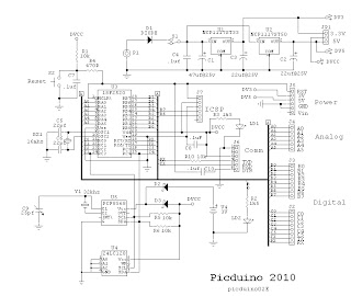
PROJECT OBJECTIVE: Replace the AVR processor on the Arduino form factor with a 28 pin 18F PIC processor. Add both an EEPROM and RTC to the design. Use thru hole, including DIP parts, to facilitate assemble.

FEATURES:
  • 18F, 28 pin PIC processor (16F optional)
  • Tiny bootloader with auto-bootloading (DS30 coming)
  • Arduino pcb form factor
  • Serial communication using breakout boards
  • Stackable connectors with Arduino compatible pinout
  • Dual LDO regulators for 3.3V and 5V.
  • Power switch, 300ma
  • Jumper for comm port power
  • Onboard I2C RTC and EEPROM
  • ICSP connector at front
  • Reset switch accessible at front
  • Testing LED on B0 at front

INTRODUCTION: Initially, the18F2520 will be used since there is an available Tiny bootloader that we have been using with good results. Presently, we are testing the 18F25K22 with the DS30 bootloader.

This design uses the Arduino physical stacking connectors, without change, except for some signal assignments. The USB circuit which is incorporated on the Arduino has not been incorporated on the Picduino, but will be contained on a breakout board allowing both RS232 and USB serial communication. The RS232 breakout will be available with the initial project and for USB communication the Sparkfun DEV 09716 will be used. This will provide the same USB functionality as the Arduino with the exception of powering the Picduino from the USB port.

The 18F2520, 18F25K22 and 18F25K20 use 5V and 3.3V respectively; therefore, dual LDO regulators have been provided. Dual regulators, also seem reasonable, since there may be shields requiring both voltages. A switch is used to apply power to the board.

Since the intended use for the Picduino is as a base unit for the Rainwater Level Monitor project, an RTC and EEPROM were incorporated on the main Picduino PCB. Because the Picduino can operate at 3.3V the RTC, DS1307 can't be used and has been replaced by the PCF8563 in the design

For software development, several compilers can be used including: OS Basic, MikroBasic Pro, Swordfish and Proton. If you use the 18F25K20 or 18F25K22, then the free Amicus compiler can be used. With the latest updates, PicKit2 will program the 18F25K22, see Tips and Tricks. The18F25K22 is also supported by MPLAB.

The “C” compiler used by Arduino can create compiled modules and then linked from libraries using an Include directive. Both MBP and SF can do this, but PicBasic Pro, Proton Basic, OS Basic and Amicus can't. This feature of the AVR-GCC compiler is one of the reasons that the AVR processor was picked for Arduino and why the Arduino platform is so successful. Our intention is to develop code with Swordfish and OS Basic.  

As an aside, the method of Arduino development is similar to our method described in this site. Compile the code, download it, examine its behavior, then make adjustments to the code and try again. There are code developers out there who use the AVR-GCC to create modules that the uninitiated can use. Most of the hard work is done by those developers. For example, writing code to generate the model train DCC signal is not simple because of the timings involved, but I am sure some developer is out there building a DCC module.

Note 1: The Arduino uses DTR of RS232 to reset the processor for an autoboot. The FTDI cable brings out RTS on pin 6 not DTR so it will not work in autoboot mode. Sparkfun sells a USB breakout board that will work (DEV-09716).


DIMENSIONS:
W: 2.7 in, L: 1.9 in, H: .5 in

SCHEMATIC DIAGRAM:


PICTURE:

Picduino without serial breakout


BILL of MATERIALS:

PCB LAYOUT:

Monday, April 23, 2012

Using a LCD Terminal for MCU Software Debugging

One of the advantages of an in circuit debugger, ICD, is the ability to monitor variables. If you are using a bootloader for development an LCD terminal can be used for that purpose. Connect the LCD terminal to an unused pin on the MCU and output the variable information using software UART code that most compilers provide. Setting a break or tight loop right after the variable output is often necessary. In time I will provide some examples of this method below.

Sunday, April 22, 2012

LCD Terminal, the GMterm II


Project GMterm II

PROJECT OBJECTIVE: To develop a serial LCD terminal written in OS Basic that will respond to the PH Anderson command set. To design a pcb for the project.

INTRODUCTION: This project started out as an attempt to produce firmware for the 16F886 that would respond to the command set of the PH Anderson serial LCD products sold as programmed 16F628 chips, except with all code written in Basic.. Andersons code was written in assembly language, used an interrupt driven buffer on the serial input and provided RS232 and TTL inputs. As mentioned elsewhere in this site, I used PHA's device to monitor variables during code development and .now I use the GMterm 2.

GMterm has all code written in OS Basic and responds to all of the PHA's commands, except for big numbers. It uses a interrupt driven barrel buffer for the input serial data stream. A pcb has also been designed to house the GMterm chip and, though, the initial design used the 16F886, the pcb can also use the 18F2420, 18F2520 and the 18F25K22. Since the code is written in Basic, conversion to the other MCU's is easy.

Since the 28 pin devices have additional I/O, other capabilities could be added to the PHA design, such as, four selectable baude rates, command controllable contrast and serial interface daughter boards.

FEATURES:
  • LCD: 1x8  to  4x40
  • Backlight control, PWM
  • Contrast control: digital or analog potentiometer.
  • I/O, direct TTL and RS232
  • Daughter board for RS232, RS485 ( full and half duplex) and USB
  • I2C with branch, 16 address, 6 meters max.( not implemented)
  • USART select: 8 or 9 bit
  • baude: 2400, 9600, 19.2k, 38.4k
  • GPIO
  • Command Set: Basic and extended
  • Tiny Bootloader
  • MCU: 16F886, 18F2420, 18F2520 and 18F25K22
  • Requires external regulated power.

DIMENSIONS:
W 1.5 inch, L 2.8 inch

PICTURE:


SCHEMATIC:


SLBB DEVELOPMENT SETUP:
Intro: The solderless breadboard, slbb,  setup uses the uLab28 PIC and is pictured below. This setup implements part of the circuit diagram: 16F886, LCD, contrast pot and a speaker. If you do not have a uLab28 then the entire circuit can be wired on the slbb. You will also need to provide +5V to the circuit from a separate power supply or a regulator wired on the slbb.


Development setup for LCD terminal using uLab28.


What's Needed
  1.  SLBB with 830  or 1660 contacts
  2.  Wart: 6 VDC @ 500ma unregulated
  3.  Addon: PWR-1 or (7805 + parts)
  4.  Addon:RS232 ( ST232CN + parts)
  5.  Microchip 16F886 with Tiny bootloader
  6.  20x4 LCD Vishay L020N4AYYHET or equivalent
  7.  Digital Pot.CAT5113LI-10-G
  8.  Oshonsoft PicSimIde Basic compiler
  9.  Tiny Bootloader
  10.  PC with a RS232 port

The LCD used in our setup has a SIP connector at the top of the display similar to the Vishay part above. The sip can be plugged directly into the slbb or use adapters with a ribbon cable. The Simple Menu project uses adapters.

If a 7805 regulator will be used in your setup, then a 7.5VDC wart may be needed. This can be determined by checking the voltage drop across the regulator. The backlight on the LCD draws the greater power, about 200ma. If you are having overheating, change the backlighting level or turn it off.

Step 1) Wire a basic setup including: processor and RS232 interface. Connect a LED with resistor from B0 to ground. The uLab28-PIC has all of this on-board.
Step2) Compile a LED blink routine and download to make sure bootloader and hardware are working properly. There is a blink routine in zip file.
Step3) Complete basic SLCD wiring while referring to Basic circuit diagram. See zip file.


PDF DATASHEETS:

LINKS:
Tiny Bootloader
Oshonsoft

LISTING:


PCB LAYOUT:


Friday, April 20, 2012

Rain Water Tank Level Monitor

This a work in progress.

Design Spec: To measure rainwater tank water level in a single tank. Two different measurement methods will be incorporated: pressure and sonic ranging. The data will be shown in height and volume. Using a battery backup realtime clock, data will be logged twice daily over the period of one year. An RS232 port will allow the data to be downloaded to a  computer for analysis. A large character LCD will provide continuous display of time and water level.

Components
1) Two different RTC's are being tried: DS1307 and PCF8563.
2) A 24LC512 for memory storage.
3) PIC18F2520 with Tiny bootloader
4) 16x2 or 20x2 LCD: Vishay 016N002L or 020N002L

Software
1) Basic Clock: Simple realtime clock using a RTC I2C chip. 12/24 function is included. Start time is set as part of the code.

                a) Clock_DS1307_LCD_2.bas
                b) Clock_PCF8563_LCD_2.bas

2) Menu Routine: This menu routine uses 3 buttons: Select, Up, Dwn. The menu items are shown on the bottom line of the display. Execution occurs on the leading edge of button press and, following execution, waits for the button to be released. The buttons are connected to the port pins with a 10K pullup.

                Clock_menu_4.bas              This code is not complete.

3) Clock with Menu:

In Process. Code written to date can be found here in files. RTC_clock.zip

Notes 1)  The code is written using Oshonsoft Basic for the 18F2520. From this point on I wish to switch to the 18F25K22 and use either the Swordfish (preferred) or the Amicus (Proton) Basic compiler. The Swordfish would be preferred since it uses a linking loader, so that modules can be developed much like the Arduino. Unhappily OS Basic does not as yet support the 18F25K22.


Rain Water Monitor Shield Prototype.

Wednesday, April 18, 2012

DS30 Bootloader for the 18F25K22

I have been using the Tiny bootloader for my Pic projects, but have decided to change to the DS30 bootloader mainly because of its ease of use and extensive device set.

More to come.

ZIF Adapter for PicKit2

I have an older Melabs serial pin programmer which I purchased with a ZIF adapter. Though the Pic processors can be programmed in situ using the ICSP connect, if it is available, during development I find it is easiest to use a ZIF socket. To that purpose a ZIF adapter has been designed for use with the PicKit2. The ZIF adapter plugs into the PicKit2 ICSP connector and a switch on the ZIF board changes Pic number of pins, i.e., 28/40 or 20 etc.


At the moment I do not stock this board, but it is available from Batchpcb. The ZIF socket is available from several sources as well as the switch.

BOM:

  1. PCB: Batchpcb, ZIF PicKit2 Adapter
  2. ZIF Socket: Futurlec, universal 40 pin ZIF socket, ZIFU40
  3. Switch: Mouser, Slide Switch